
Introduction
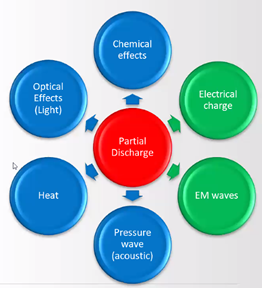
Partial discharge (PD) is a localized dielectric breakdown in an insulating material. It is caused by a high electric field stress in a small area of the insulation. PD can occur in any type of medium and high voltage insulation, including cables, transformers, and switchgear.
The occurrence of PD is usually an indicator of underlying defects within the insulation. In later stages, the PD activity itself further degrades the insulation, and is a serious problem, as it can lead to insulation breakdown and equipment failure.
PD can be detected by a variety of methods, including electrical, optical, and acoustic. Electrical methods are the most commonly used methods for PD testing of cables.
Online PD Testing
Online PD testing is the process of testing for PD while the cable is in service. This type of testing is non-invasive and does not require the cable to be de-energized.
Online PD testing is performed using sensors that are placed on the cable or near the cable terminations. The most common sensors used for online PD testing are high frequency current transformers (HFCTs) and transient earth voltage (TEV) sensors.
Online PD Testing using HFCTs and TEVs
|HFCTs are used to measure high frequency currents that are generated by PD. HFCTs are typically clamped around the cable or ground strap. The HFCT converts the high frequency PD current flowing in the cable or ground strap into a voltage signal that is proportional to the current.

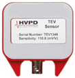
TEV sensors are used to detect the effect of the electromagnetic radiation that is generated by PD. TEVs are typically placed near the cable terminations. The electromagnetic radiation from the PD generates transient voltages on surrounding metal surfaces. The TEV is a capacitive sensor that generates a voltage signal that is proportional to the transient voltage generated by the radiation.
HFCTs and TEVs can be used together to provide a comprehensive online PD testing solution. HFCTs typically have a good frequency response from 100 kHz to 10 MHz, which is excellent for detecting PD activity along the entire length of the cable.
TEVs have a good frequency response from 1 MHz to 100 MHz and are used to detect PD activity at the cable terminations.
The signals from the HFCTs and TEVs are fed to a PD analyzer, which analyzes the signals to detect and measure PD activity. Proper installation of HFCTs and TEVs is critical to obtain high quality data, and is one of the most important aspects of good PD analysis, along with operational data such as ambient temperature, humidity and operational load.
Partial Discharge Signal Propagation
When PD occurs within the cable insulation, it induces high frequency currents in both the conductor and the screen of the cable. These two currents are equal in amplitude and flow in the opposite directions. In order to evaluate the PD activity, either of these current signals needs to be captured.
The can be done in two ways: by placing an HFCT around the cable earth (-ve PD current) or around the cable plus the cable earth (+ve PD current). Note that placing the HFCT around the power cable results in a cancellation of the two currents and hence no PD can be detected.
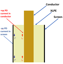
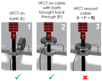
Fig. 4: Flow of PD currents in a cable and sensor placement for their detection
For the electromagnetic sensing with the TEV, it is important to place the TEV sensor near a vent, opening, joint or a barrier. This is because the transient voltage pulses generated by the EM radiation travel via skin effect and remain trapped inside the cable compartment except at these openings.
PD Representation
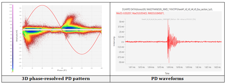
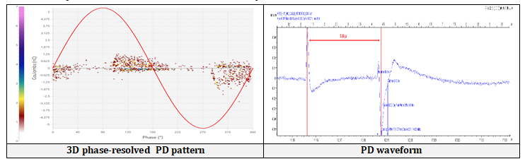
HFCTs quantify cable PD in terms of picoCoulombs (pC), while TEVs quantify termination PD in terms of dBmV. Most PD instrument manufacturers also provide 2D & 3D graphs of PD amplitude with respect to the phase of the line voltage, known as phase-resolved partial discharge plots (PRPD).
A 2D PRPD graph shows PD amplitude vs. phase angle, while 3D PRPD graphs show PD amplitude and repetition rates vs. phase angle. The latter are more common today and provide much more diagnostic information.
More advanced instruments also provide waveforms and frequencies of the individual pulses. These features make it easier to separate PD from noise as well as to distinguish between cable and termination PD.
PD Analysis
Once the PD signals from the HFCTs and TEVs have been acquired, they are analyzed to detect and measure PD activity. PD analysis must be performed in a comprehensive and scientific manner. The entire methodology is beyond the purview of this paper, but the key steps are listed below:
- Study the unfiltered PRPD patterns to determine if gross indications of PD exist
- Eliminate the noise signals using various software tools to get the filtered PRPD patterns
- Study the filtered PRPD patterns to see if the PD is internal, on the surface, or in air
- Study the PD waveforms to see if the PD is in the cable or in the terminations
- If cable PD, look for the reflection of the PD pulse to determine the location of the PD source (in terms of metres from the test end)
- Compare HFCT and TEV signals to confirm termination PD
- Compare direction of HFCT signals from different phases to determine the source
- Compare time-of-flight of multiple TEV signals to narrow down the source
PD Interpretation
The results of PD analysis are used to interpret PD activity and assess the condition of the cable. Interpretation of PD results depends on a number of factors, including the amplitude of the PD signal, the cable type, the operating conditions, and the type of PD.
Currently, there are no limits specified for PD activity in cables in any standard for online testing. In general, XLPE & EPR cables should be free of measurable PD, while PILC cables can withstand significant PD. Even in XLPE/ EPR cables, joints and terminations can withstanding some level of PD.
The Oil Industry Safety Directorate and Saudi Aramco have published some guidelines intended for offline testing, but which could be interpolated for online testing also. The ANSI-NETA Maintenance Testing Specifications contain limits for switchgear tested with HFCTs and TEVs, but not for cables. Hence, it is strongly recommended to test and compare similar cables as well as trend them over time.
Benefits of Online PD Testing
Online PD testing offers a number of benefits. These benefits include:
- Non-invasive: Online PD testing does not require the cable to be de-energized, so it can be performed without disrupting service.
- Continuous monitoring: Online PD testing can be used to monitor the cable continuously for PD activity. This enables for early detection of PD problems, which can help to prevent cable failure.
- Trigger for detailed investigation: Detecting PD at an early stage provides an alert for scheduling more comprehensive offline testing.
- Assessment of operational impact: Online PD testing can be trended against operational parameters such as temperature, humidity, load, etc., giving an understanding of their impact on the cable’s life.
- Lower cost: As the instruments for these are highly portable and no outage is required, large number of cables can be tested easily at much lower costs.
Applications of Online PD Testing
Online PD testing can be used on a wide variety of cables, including:
- High voltage (HV) power cables
- Medium voltage (MV) power cables
- Underground cables
- Submarine cables
- Wind turbine cables
- Industrial cables
- Connected switchgear
- Connected transformers
Limitations of Online PD Testing
While online PD testing offers a number of benefits, one should keep its limitations in mind so as avoid unrealistic expectations. Some of the limitations include:
- If the cable earth strap is not accessible, then test results have limited accuracy
- Water treeing and physical damage cannot be detected
- Noise elimination requires high expertise
- On long cables, it can be difficult to determine the PD location
- Sensitivity to low level PD is not as high as that of an offline test
Case Studies
Defective joint in new 33 kV cable at a refinery
A newly installed, 1.74 km 33 kV cable at a refinery had high tan delta in 2016. After 4 months, It failed at a joint. After joint replacement, it passed the withstand test and had good tan delta values. However, PD was detected in the remade joint. As time did not permit to replace the joint, it was decided to monitor the same through online PD. Online testing detected the PD activity accurately, enabling energization of the critical feeder with monitoring until a fresh outage could be planned.
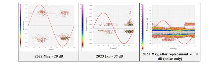
During routine online PD testing, a 220 kV termination was found to have high PD. Periodic monitoring showed a rising trend, after which the termination was replaced during a planned outage. Had this gone unnoticed, the termination would likely have failed in operation, leading to plant losses in crores!
Conclusions
Online Partial Discharge testing is a valuable tool for detecting and monitoring PD activity in cables. It is a non-invasive, continuous, accurate and cost-effective method of assessing cable health.
HFCTs and TEVs are the ideal sensor combination to assess the entire cable length. Proper placement of the sensors (HFCT on cable earth and TEV near to a vent/ barrier/ opening) is critical for sensing the PD signals.
Online PD testing can be used on a wide variety of cables, including HV and MV power cables, underground cables, submarine cables, wind turbine cables, and industrial cables.
REFERENCES
[1] R. R. Mackinlay & C. M. Walton; “Some advances in PD Monitoring for high voltage cables”, IEE Cable life conference, Capenhurst, UK, 21 April 1998.
[2] M. Seltzer-Grant, D. Denissov, R. Mackinlay, F. Petzold, L. Renforth & H. Schlapp; “On-Line Continuous Monitoring for In Service Distribution Class Cables and Switchgears,” Proceedings of the 21st International Conference on Electricity Distribution (CIRED), Frankfurt, 6-9 June 2011.
[3] Paoletti, G. & Golubev, A., “Partial discharge theory and applications to electrical systems,” Pulp and Paper Industry Technical Conference, 1999. Conference Record of 1999 Annual, vol., no., pp. 124-138, 21-25 Jun 1999.
[4] Davies, N. & Jones, D.; “Testing Distribution Switchgear for Partial Discharge in the Laboratory and the Field,” Electrical Insulation, 2008. ISEI 2008. Conference Record of the 2008 IEEE International Symposium on, vol., no., pp. 716-719, 9-12 June 2008.
[5] Walton C, Carter S., Michel M. & Eastham C.; “Avoidance of MV switchgear Failure Case Studies of On-line Condition monitoring “, Proceedings of the 20th International Conference on Electricity Distribution (CIRED), Prague, 8-11 June 2009.
[6] N. Ahmed & N. Srinivas, “On-line Partial Discharge Detection in Cables”, IEEE Trans. On Dielectric and Electr. Insul., Vol. 5, No. 2, 1998.
[7] N. Ahmed and N. Srinivas, “Partial Discharge Measurement in Distribution Class Extruded Cables, 1999 IEEE T&D Conference, pp 46-51, New Orleans, 1999.